头部背景图片

What Are the Top 5 CNC Machine Brands?

2026-06-02

When buyers ask, "Which CNC brand should I trust?" – here are 5 globally recognized names in woodworking CNC machines:

1.Homag (Germany)

Market leader in industrial panel processing. Known for high automation, but very expensive.

2.Biesse (Italy)

Excellent for nesting and edgebanding. Reliable, stylish, and built for European standards.

3.SCM (Italy)

Versatile CNC solutions for cabinets, doors, and furniture. Strong after-sales in many countries.

4.Morbidelli (Italy)

High-speed CNC nesting machines. Popular among large furniture factories.

5.Haas (USA)

Trusted for general CNC routing. Great for metal and wood hybrid shops.

But here’s what many people don’t tell you:

These top brands can cost 80,000–200,000+. For many small to mid-sized workshops, that’s not realistic.

That’s why more buyers today are looking at China CNC nesting machines.

Why?

✅ Same key components (German servos, Japanese bearings, vacuum tables)

✅ Advanced nesting software (AlphaCam, CAD/CAM compatible)

✅ 40–60% lower price – factory direct

✅ CE certified, stable performance for cabinet, MDF, plywood, and solid wood

We are a Chinese factory making CNC nesting machines for over 10 years. Not a trading company. You get real factory support, customized options, and fast delivery.

📩 Looking for a reliable but affordable CNC solution?

Send us a message for factory-direct pricing.


What is a CNC Machine Router?

2026-06-02
CNC router

In simple terms, a CNC router is a computer-controlled carving machine. Imagine a handheld woodworking router, but instead of moving it by hand, a computer guides it automatically along three directions (X, Y, Z axes).


How does it work?

Design: You draw a part on a computer (CAD).

Convert: The software turns that drawing into machine language (CAM/G-code).

Cut: The CNC router reads the code and automatically cuts the exact shape from wood, MDF, acrylic, or even aluminum.

CNC woodworking equipment

Why do factories love them?

⚡ Speed & Precision: They work 10x faster than manual labor with near-zero error.

🔄 Repeatability: Need 1,000 identical cabinet doors? The machine delivers every single time.

🎨 Complexity: Create 3D reliefs, dovetails, and intricate patterns impossible to do by hand.


What can you make?

✅ Kitchen cabinets & wardrobes

✅ 3D signage & logos

✅ Acrylic/PVC parts

✅ Furniture molds


As a professional CNC woodworking equipment manufacturer, we provide complete solutions—from entry-level models to automatic production lines. Are you looking to upgrade your workshop?


As a professional manufacturer of CNC woodworking equipment, we offer complete solutions ranging from entry-level models to automated production lines.


Vibration measurement of centrifugal pumps and analysis of typical failures

2026-06-02

Understand vibration measurement of centrifugal pumps, common faults, and their causes.


Preface

Pumping systems are critical equipment in industrial processes, with various types of pumps designed to meet diverse production requirements. Among these, centrifugal pumps are the most widely used industrial pumps. Classified as power pumps, they can be further subdivided into axial-flow and radial-flow pumps, featuring multiple characteristics such as single-stage or multi-stage configurations, vertical or horizontal arrangements, and open-, semi-open-, or closed-type impellers.

A centrifugal pump is a rotating hydraulic machine that converts the mechanical energy of its impeller into kinetic or pressure energy by transferring it to an incompressible fluid. The fluid enters the center of the impeller via the suction pipe; the impeller, equipped with a series of blades, utilizes centrifugal force to propel the fluid toward the discharge pipe. During this process, the fluid passes through the pump's volute or casing, and in multi-stage pumps, through additional impellers.


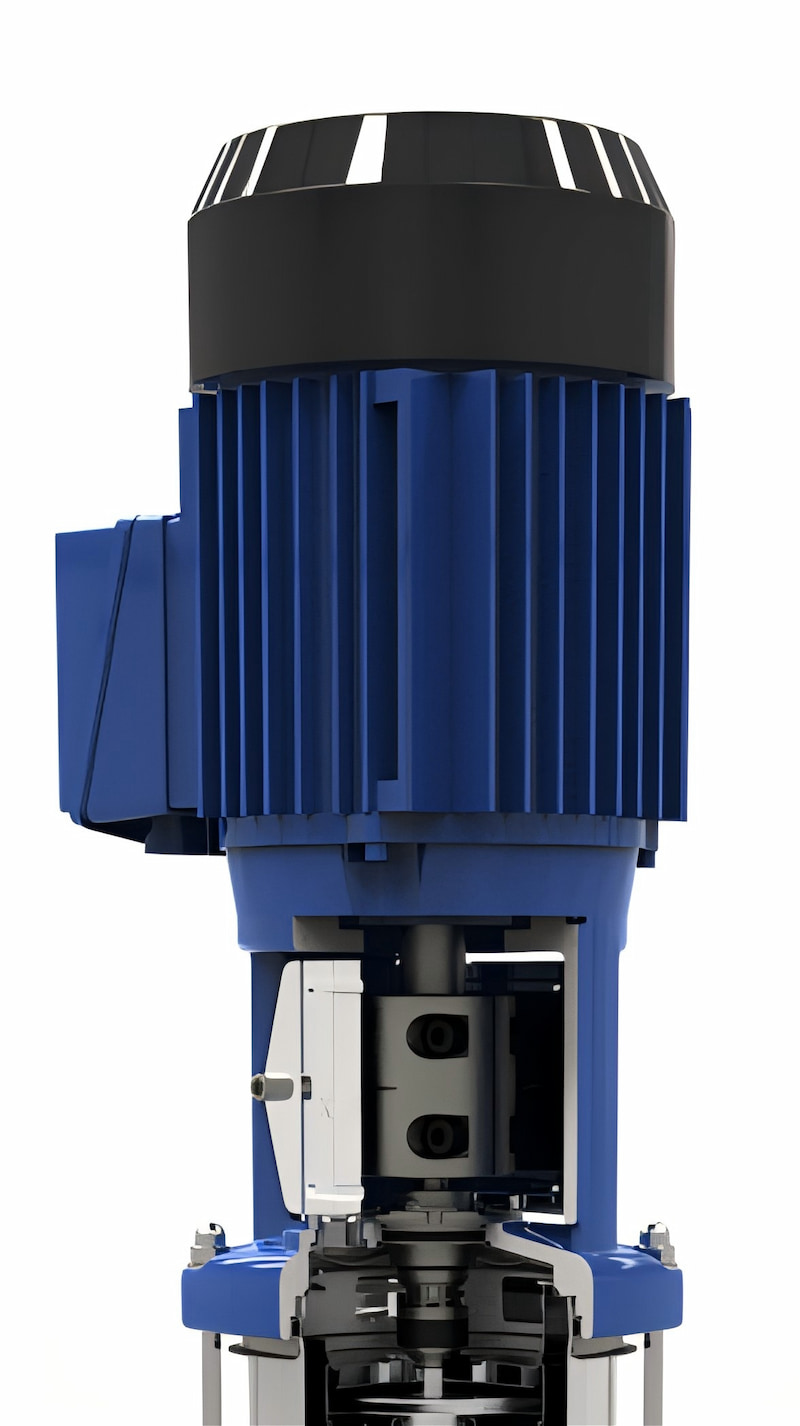
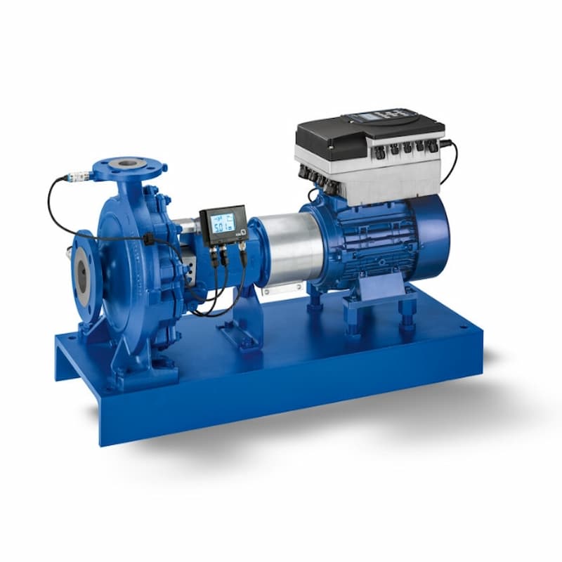
Main components of a centrifugal pump


The main components of a centrifugal pump include:

1. Inlet pipe

2. Impeller

3. Shaft

4. Housing or volute

5. Bearing

6. Bearing box

7. Mechanical seal

8. Discharge pipe


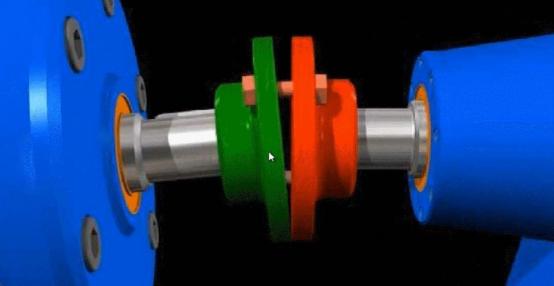
Figure 1: Main components of the centrifugal pump


Figure 2: Main Components of the Centrifugal Pump


Vibration Measurement Point


In a centrifugal pump, the vibration measurement point must align with the shaft centerline on the bearing housing (perpendicular to the shaft centerline). Ensure the sensor is securely mounted on a robust component and measure vibrations in all three directions—horizontal (H), vertical (V), and axial (A)—to obtain accurate vibration data.


Figure 3: Vibration measurement point


Safety is the paramount consideration when selecting vibration monitoring points. On the coupling side, axial measurements should not be taken unless adequate safety measures are in place. Certain pump components—such as mechanical seals and associated piping—are typically hot; therefore, direct contact with these parts must be avoided. Additionally, measurement instrument cables should not come into contact with hot pipelines to prevent fire hazards.


Figure 4: Vibration measurement point


For small pumps, some analysts measure the condition of the pump bearings at a single measurement point.


Typical failure modes of centrifugal pumps


1. Imbalance


In centrifugal pumps, imbalance is typically caused by one of the following reasons:


1) Uneven impeller wear (e.g., cavitation) or blade fracture;

2) Poor coupling condition with wear or deformation.

3) Defective motor rotor winding;

4) Errors in the workshop balancing procedure;

5) Use of inappropriate standards or improper balancing masses


When imbalance is detected in a centrifugal pump, the following measures are recommended:


1) Inspect the wear condition of the impeller and analyze its cause;

2) Examine the vibration of the coupling and its overall condition.

3) Inspect the workshop's balancing procedures and their quality grades


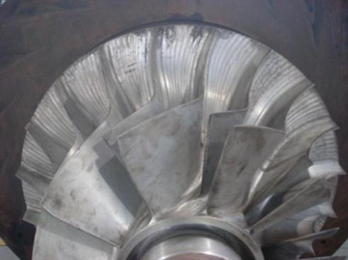
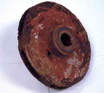
Figure 5: Worn pump impeller


2. Not centered


In centrifugal pumps, misalignment is typically caused by one of the following reasons:


1) Improper installation or incorrect alignment procedure;

2) Pipeline stress;

3) Soft feet;

4) Thermal expansion of the pump itself or its pipelines

5) Lack of employee training; 6) Inappropriate or uncalibrated measuring instruments


When misalignment of the centrifugal pump is detected, the following measures are recommended:


1) Verify the alignment procedures and application standards used;

2) Check for pipeline stresses and flexible feet in pumps and motors.

3) If safety conditions permit, measure the alignment status immediately after the machine stops or when the engine is hot.

4) Record the alignment displacement (i.e., thermal expansion) during machine heating/temperature rise.


Figure 6: Centrifugal Pump Centering Inspection


3. Bearing issue


In centrifugal pumps, bearing issues are typically caused by one of the following reasons:


1) Improper installation;

2) Inadequate lubrication;

3) Contamination of grease or lubricant with particulate matter;

4) Excessive temperature

5) Not neutralizing/and/or unbalanced;

6) Improper bearing selection


When bearing issues are detected in a centrifugal pump, the following measures are recommended:


1) Replace the bearing and conduct a root cause analysis;

2) Inspect the condition of the bearing lubricating grease.

3) Inspect the bearing installation process;

4) Evaluate the bearing lubrication method.

5) Confirm the alignment and balance of the pump;

6) Check whether the operating conditions are suitable for bearing use.


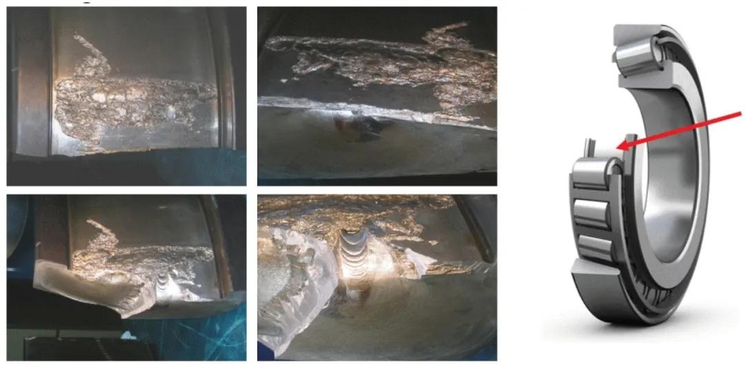
Figure 7: Removal of the defective bearing


4. Leakage


In most cases, leakage in centrifugal pumps occurs at the mechanical seal. The causes of seal damage may include:


1) High vibration caused by misalignment or imbalance;

2) Improper installation

3) Sealing overheating during no-load or dry operation; 4) Improper sealing selection


When sealing issues are detected in a centrifugal pump, the following measures are recommended:


1) Check the alignment and balance of the pump;

2) Ensure proper installation of the mechanical seal.

3) Avoid operating the pump in a dry state;

4) Verify that the operating conditions meet the requirements of the mechanical seal.


5. Rotational loosening


In centrifugal pumps, rotational loosening is typically caused by one of the following reasons:


1) Excessive bearing wear;

2) Improper installation;

3) Inappropriate bearing selection;

4) Poor fit of the bearing housing or excessive manufacturing tolerances


When a rotational clearance is detected in the centrifugal pump, the following measures are recommended:


1) Inspect the condition of the bearing;

 2) Check for wear or deformation in the bearing housing.

3) Check whether the selection and installation of bearings comply with specifications.


Figure 8: Inspect the clearance (wear condition) between multi-stage pump moving/standing components


6. Structural Issues


In centrifugal pumps, structural loosening is typically caused by one of the following reasons:


1) Poor foundation;

2) Deformation or distortion of the base

3) Wear of pump support or silencer block;

4) Loosening bolts causing soft feet


When structural loosening of the centrifugal pump is detected, the following measures are recommended:


1) Strengthen the structure of the centrifugal pump support;

2) Repair the foundation/base of the centrifugal pump

3) Replace the supports, thermal insulation materials, or sound-absorbing blocks;

4) Use a torque wrench to tighten the bolts of the centrifugal pump.


Figure 9: Optimal foundation of the centrifugal pump


7. Fluid dynamics problems


Hydraulic issues in centrifugal pumps are diverse and typically arise from one of the following causes:


1) Cavitation;

2) Recirculation (i.e., internal reflux);

3) Overload;

4) Unstable inlet flow pattern;

5) Pump operation exceeding design specifications


When hydraulic issues are detected in a centrifugal pump, the following measures are recommended:


1) Check the suction conditions of the centrifugal pump;

2) Inspect the impeller and pump housing for any damage.

3) Verify whether the operating conditions (flow rate and pressure) meet the design requirements of the centrifugal pump.


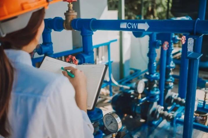
Figure 10: Some hydraulic issues in centrifugal pumps can be identified by checking operating conditions, performing visual inspections, and reading pressure gauge readings.


8. Other prediction techniques


The inspection of centrifugal pumps must be comprehensive, covering dynamic, hot-state, and operational behaviors. The following techniques are equally applicable to centrifugal pumps:


Prediction Technology

Detectable Faults

Visual Inspection

Leakage, cleanliness, abnormal noise, loose parts, instrument readings. Operational variables such as performance and efficiency (pressure, flow rate, electric current, temperature) can also be included.

Thermal Imaging Technology

Excessive heat (mechanical seal or bearing)

Ultrasonic Testing

Bearing problems

Oil Analysis and Tribology Analysis

Degradation of lubricants (grease), water content, contaminants, bearing wear


Are Forged Wheels Worth the Investment for Daily Drivers?

2026-05-22

Forged wheels are often associated with race cars, luxury vehicles, and high-performance builds. But many car owners have a more practical question: are forged wheels really worth it for daily driving?

The answer depends on what you expect from your wheels. If you only need a basic replacement wheel, a standard cast wheel may be enough. But if you care about strength, weight, fitment, and a cleaner custom look, forged wheels can be a meaningful upgrade even for a daily driver.


A forged wheel is made by applying high pressure to a solid piece of aluminum, rather than pouring molten aluminum into a mold like a cast wheel. This process helps create a denser and stronger wheel structure. For daily use, that strength matters. City roads, potholes, speed bumps, rough pavement, and unexpected impacts are all part of normal driving. A well-made forged aluminum wheel can offer better durability while keeping the wheel weight lower than many cast alternatives.


Cast vs forged wheels manufacturing comparison

Weight is one of the biggest reasons drivers choose forged wheels. Lighter wheels reduce unsprung weight, which may help the suspension respond more efficiently. In real driving, this can contribute to sharper steering feel and a more responsive driving experience. The difference may not turn a daily car into a track car, but it can make the vehicle feel more refined, especially on premium sedans, SUVs, and performance models.


Another important benefit is fitment. Custom forged wheels can be made according to the vehicle’s specifications, including diameter, width, offset, bolt pattern, and brake clearance. This is especially useful for owners who want a flush stance without relying on spacers or unsuitable factory sizes. For example, many customers choose 19 inch forged wheels or 20 inch forged wheels to improve the appearance of the car while still keeping daily comfort in mind.


Appearance is also part of the value. Forged wheels are highly customizable, from spoke design to surface finish. Options such as brushed, polished, matte black, bronze, gunmetal, and two-tone finishes allow the wheel to match the style of the car. For daily drivers, this means the upgrade is not only about performance, but also about making the vehicle look more personal and premium.

Of course, forged wheels cost more than cast wheels. That is the main reason some drivers hesitate. But the higher price also reflects the material, manufacturing process, engineering work, and customization involved. If you plan to keep your vehicle for several years, or if you are building a car with specific fitment and style requirements, forged wheels can be a long-term investment rather than just a cosmetic upgrade.


So, are forged wheels worth it for daily drivers? For owners who want the lowest-cost option, they may not be necessary. But for those who value lightweight performance, stronger construction, accurate fitment, and a custom appearance, forged wheels are definitely worth considering.

At Rimpower, we manufacture custom forged wheels using T6061-T6 aluminum, with fitment support for luxury cars, SUVs, and performance vehicles. Each order can be customized based on your vehicle data, design preference, and finish requirements.


How to Align a Centrifugal Pump and Motor Shaft in 5 Easy Steps

2026-05-19


Proper pump shaft alignment is critical to preventing severe vibration, bearing wear, and premature mechanical seal failure. To align a pump in 5 steps:


1) Lock out power

2) Perform a rough visual alignment

3) Mount dial indicators or a laser alignment tool

4) Add or remove motor shims for vertical adjustment

5) Adjust horizontally, then perform a final torque and re-check


Even the highest quality industrial pumps will destroy themselves if they are improperly installed. Misalignment between the pump shaft and the motor shaft places immense stress on the coupling. Over time, this stress translates into excessive vibration, leading to catastrophic mechanical seal failure and broken bearings.


To ensure optimal industrial fluid control and extend the lifespan of your equipment, follow this 5-step guide to precision shaft alignment.


Step 1: Safety Lockout and Preparation


Before touching any mechanical components, completely lock out and tag out (LOTO) the motor's power supply. Clean the baseplate, the motor feet, and the pump casing. Remove any rust, dirt, or old shims that could cause a "soft foot" (where the motor does not sit perfectly flat on the base).


Step 2: Rough Visual Alignment


Do not attach the coupling yet. Place a high-quality straightedge across the coupling halves at the top, bottom, and both sides. Use this visual check to move the motor roughly into position. This saves time before setting up sensitive precision instruments.


Step 3: Mount Your Precision Tools


While traditional dial indicators are highly accurate, modern laser alignment tools are faster and eliminate mathematical calculation errors. Mount the laser brackets securely to both the pump shaft (stationary machine) and the motor shaft (movable machine). Rotate the shafts together to take readings at the 9, 12, and 3 o'clock positions.


Step 4: Correct Vertical Misalignment (Shimming)


The laser tool will indicate how far off the motor is vertically. To fix this, you must carefully add or remove stainless steel shims under the motor feet. Always use the fewest number of shims possible (ideally no more than three under one foot) to prevent a spongy foundation. Once shimmed, tighten the motor bolts to check if the vertical alignment is within the manufacturer's tolerance.


Step 5: Correct Horizontal Misalignment and Final Check


With the vertical height corrected, gently tap the motor side-to-side using jack bolts (never hit the motor with a heavy hammer) to achieve horizontal alignment. Once both horizontal and vertical axes are in the green zone on your laser tool, fully torque down all motor bolts. Crucial: Always do one final laser sweep after tightening the bolts, as the torquing process can slightly shift the motor.

How to calculate the total cost of ownership (TCO) for industrial pumps

2026-05-19


The initial purchase price of an industrial pump accounts for only 10% of its Total Cost of Ownership (TCO). The remaining 90% is consumed by energy costs, maintenance, and downtime over its lifespan. To calculate TCO, use the formula: TCO = Initial Cost + Installation + Energy Costs + Maintenance + Downtime Costs. Upgrading to IE3/IE4 motors significantly lowers long-term expenses.


When B2B procurement teams look to upgrade their fluid handling systems, they often focus entirely on the upfront purchase price. However, in the heavy machinery sector, buying the cheapest pump usually results in massive financial losses over the next decade. Understanding the true financial impact requires calculating the Total Cost of Ownership.


Here is a breakdown of how to accurately assess the real cost of your energy-efficient pumps and why investing in quality upfront pays massive dividends.


The TCO Breakdown: Where Does the Money Go?


Over a typical 10-to-15-year lifecycle, the costs associated with an industrial pump break down approximately like this:


● Initial Purchase & Installation: ~10% to 15%

● Maintenance & Repairs: ~15% to 20%

● Energy Consumption: ~65% to 75%


1.Energy Costs: The Silent Budget Killer


Because industrial pumps often run 24/7, electricity is by far the largest expense. A standard pump operating continuously can consume its own purchase price in electricity in just one year. When calculating TCO, always factor in the efficiency rating of the motor. Upgrading to an IE3 or IE4 high-efficiency motor might cost 20% more upfront, but it dramatically reduces the lifetime energy bill.


2. Maintenance and Spare Parts


Cheap pumps use inferior mechanical seals, bearings, and casting materials. When calculating pump lifecycle costs, you must estimate the frequency of seal replacements and oil changes. High-quality pumps designed with heavy-duty shafts experience less deflection, which means their mechanical seals last twice as long, drastically reducing your spare parts budget.


3. The Cost of Unplanned Downtime


This is the most critical variable. If a cheap boiler feed pump fails and shuts down your entire manufacturing plant, the lost production revenue can amount to tens of thousands of dollars per hour. When evaluating a supplier, factor in the reliability of the equipment and the speed of their spare parts delivery.


How to Lower Your TCO


To protect your bottom line, stop treating industrial pumps as disposable commodities. Always size the pump to operate at its Best Efficiency Point (BEP). Consider installing Variable Frequency Drives (VFDs) to adjust pump speed based on actual demand, rather than running at full speed and throttling with valves. By spending a little more during the procurement phase, you can save hundreds of thousands of dollars in operational costs.

Top 5 Causes of Centrifugal Pump Vibration and How to Fix Them

2026-05-19


Excessive pump vibration is an early warning sign of catastrophic failure. The top 5 causes are shaft misalignment, impeller imbalance, cavitation, bearing wear, and bent shafts. To fix vibration quickly, engineers should first check the pump shaft alignment using a laser tool, ensure the NPSHa is sufficient to prevent cavitation, and inspect the impeller for accumulated debris or wear.


When a horizontal centrifugal pump begins to vibrate beyond its acceptable limits (typically measured in inches per second or mm/s), it will rapidly destroy mechanical seals and bearings. Addressing vibration early saves thousands of dollars in unplanned downtime. Here is our expert diagnostic guide.


1.Shaft Misalignment (The #1 Culprit)


If the motor shaft and pump shaft are not perfectly aligned, the coupling will bind, causing a distinct radial vibration.

● The Fix: Never rely on a straightedge. Use a precision laser alignment tool to correct both vertical and horizontal offset. Always re-check alignment after the pump reaches its standard operating temperature due to thermal expansion.


2. Impeller Imbalance


Impellers can become unbalanced for two reasons: manufacturing defects or operational wear. In wastewater applications, rags or solid debris can stick to one side of the impeller, causing a massive weight imbalance.

● The Fix: Open the casing and physically clean the impeller. If pumping abrasive fluids, check for uneven erosion and replace the impeller if necessary.


3. Pump Cavitation


If the vibration sounds like rocks passing through the casing, you are experiencing cavitation. This happens when the suction pressure drops too low, causing the fluid to boil and collapse violently.

● The Fix: Clean the suction strainer, increase the fluid level in the supply tank, or reduce the fluid temperature to lower its vapor pressure.


4. Bearing Wear and Failure


Worn bearings will produce high-frequency vibrations and a distinct whining noise. This is usually a secondary failure caused by misalignment or poor lubrication.

● The Fix: Drain the bearing housing, check for water contamination (which destroys the oil's viscosity), and replace the bearings and lip seals immediately.


5. Pipe Strain

If the suction or discharge piping is not properly supported, the heavy pipes will rest their weight directly on the pump casing, twisting it out of alignment.

● The Fix: Ensure all industrial pump maintenance protocols include checking pipe hangers and expansion joints. The pump flange should never bear the weight of the piping system.


What is Net Positive Suction Head (NPSH)? A Simple Explanation for Beginners

2026-04-30

Net Positive Suction Head (NPSH) is the measure of pressure available at the suction side of a pump to prevent the liquid from boiling and causing cavitation. To ensure safe operation, the NPSH available (NPSHa) in your system must always be strictly greater than the NPSH required (NPSHr) by the pump manufacturer.

For many young engineers and procurement managers, Net Positive Suction Head is one of the most confusing terms in fluid dynamics. However, misunderstanding this concept is the leading cause of pump cavitation, which can destroy a brand-new impeller in a matter of weeks. Here is a simplified breakdown of what NPSH means and how to calculate it.


NPSHr vs. NPSHa: What is the Difference?

There are two sides to the NPSH equation: the pump's requirement and the system's reality.

● NPSHr (Required): This is determined by the pump manufacturer. It is the minimum pressure required at the suction eye of the impeller to keep the fluid from vaporizing. You will find this value on the manufacturer’s centrifugal pump performance curve.

● NPSHa (Available): This is determined by your specific piping system. It is the absolute pressure of the fluid available at the pump inlet, minus the vapor pressure of the liquid.


The Golden Rule of NPSH

For a pump to operate smoothly without cavitating, the formula is simple: NPSHa > NPSHr. Generally, engineers recommend that NPSHa should be at least 1 meter (or 3 feet) higher than NPSHr to provide a safe operating margin.


How to Calculate NPSHa

While exact calculations require engineering software, the basic formula is:

NPSHa = Atmospheric Pressure + Static Head (or Lift) - Friction Loss - Vapor Pressure

1. Atmospheric Pressure: The pressure of the air pushing down on the fluid source.

2. Static Head: The physical height of the fluid above the pump centerline. (If the pump is pulling fluid up from a pit, this becomes a negative value).

3. Friction Loss: The pressure lost as fluid rubs against the inside of the suction pipes, elbows, and valves.4. Vapor Pressure: The pressure at which the liquid boils. Hotter liquids boil easier, meaning they have a higher vapor pressure, which drastically lowers your NPSHa.


Why This Matters for Your Factory

If your NPSHa falls below the NPSHr, the fluid will instantly turn into vapor bubbles inside the pump. As these bubbles hit the high-pressure zone of the impeller, they collapse with immense force, tearing away metal and ruining the mechanical seals. Always calculate your system's NPSHa before ordering a new pump to guarantee a long, maintenance-free lifecycle.

Access for Precision Integrating Safe Climbing Systems and Equipment Platforms in Radar Towers

2026-04-27

In the world of critical radar infrastructure, precision is everything. Modern radar systems—whether for meteorological monitoring, air traffic control, or defense—demand an exceptionally stable platform. Even minute structural vibrations or sway in a radar tower can introduce phase errors, distort beam patterns, and degrade data quality【7+L9-L12】. Yet these same towers must also be accessible. Technicians need to climb them regularly for calibration, antenna maintenance, and emergency repairs. The challenge is to integrate safe climbing systems and equipment platforms into the tower's structural envelope without compromising the stiffness that radar precision demands.

radar support tower

The Tension Between Access and Stiffness

Radar support structures are governed by stringent dynamic requirements. A tower's natural frequency must be kept sufficiently high, and well separated from forcing frequencies generated by the rotating antenna and environmental wind loads, to avoid resonant coupling that would smear radar images. Every added component—a ladder rung, a platform support bracket, a cable guide—alters the structure's mass and stiffness distribution. Poorly designed access features can introduce local flexibility or add mass in locations that lower critical natural frequencies.

A radar tower is engineered not just to carry weight, but to resist deformation under dynamic loads with exceptional rigidity. The natural frequency is a function of stiffness and mass. For heavy radar antennas and radomes, reducing mass is often impractical, so the primary lever is to maximize structural stiffness. Access features must therefore be embedded into the tower's primary structural logic rather than treated as afterthoughts.


radar support tower


Regulatory Framework for Safe Access

Radar towers must comply with safety standards that are evolving toward more effective fall protection. The ANSI/ASSE A10.48 standard provides comprehensive safety guidance for communication structures, including antenna and antenna-supporting structures, covering fall protection and rescue, climbing facilities, and training. The 2023 revision of this standard, effective January 1, updated safety practices for construction, demolition, modification, and maintenance.

OSHA regulations require 100% fall protection for personnel working at heights above 6 feet. For fixed ladders over 24 feet, the regulatory trend has shifted decisively: ladder cages are being phased out, with a 2036 deadline for their replacement on new installations and major modifications. Cages do not arrest vertical falls and complicate rescue, making modern cable- or rail-based systems the preferred solution.


Choosing the Right Climbing System

For radar towers, not all climbing safety solutions are equal. Vertical cable and rail systems have become the industry standard because they provide continuous attachment without requiring the user to disconnect at intermediate points. Tractel's FABA™ fall arrest systems allow for safe climbing on fixed vertical ladders at any height on towers, masts, and pylons. The stopcable® system features a detachable fall arrester with built-in energy absorber that locks instantly on the cable upon a fall, minimizing free-fall distance. MSA Safety's Latchways® systems (LadderLatch and TowerLatch) incorporate a patented starwheel component that enables smooth movement through cable guides without pulling cable out of the guides.


System Type Fall Protection Mechanism Suitability for Radar Towers
Fixed Ladder (No Protection) None—relies on 3-point contact Not acceptable—fails regulatory compliance
Ladder with Cage Physical barrier prevents sideways falls Phased out—does not arrest vertical falls; complicates rescue
Vertical Cable/Rail System Harness-mounted fall arrester slides on cable/rail Recommended—arrests falls within inches; hands-free climbing; minimal stiffness impact
Personal Fall Arrest System (PFAS) Harness + lanyard attached to anchor point Supplemental—suitable for platform work but not as primary climbing system

radar support tower


Equipment Platforms: Stiffening Rather Than Compromising

Radar towers typically feature multiple platforms: a lower platform for equipment access and an upper platform at the radome level for antenna installation. These platforms serve as maintenance work areas and provide mounting points for ancillary equipment. From a structural perspective, they should be integrated as stiffened diaphragms—their floor beams and bracing must contribute positively to the tower's overall rigidity.

Key design principles for platforms in radar applications:

  1. · Full-perimeter bracing: Platforms should be tied into all tower faces with cross-bracing or stiffened decking to act as horizontal stiffening rings. This prevents local mode shapes that could otherwise reduce natural frequencies.

  2. · Load transfer: Platform loads must be transferred into tower legs via dedicated connection nodes, not through diagonal bracing alone. This ensures predictable force paths and avoids unintended stress concentrations.

  3. · Open steel grating: Preferred over solid plate because it reduces wind load accumulation, improves visual inspection of members below, and sheds ice more readily. The open design also minimizes added mass, supporting the goal of maximizing stiffness-to-weight ratio.

Advanced bracing patterns—such as K-bracing or X-bracing—are analyzed and optimized to ensure a stiff, robust platform that minimizes deflection under operational loads. Platforms also serve as rescue staging areas—required resting points on tall ladders, typically every 9 to 12 metres—where a worker can rest or await assistance.


radar support tower


Lightning Protection Integration

Radar towers are often sited in exposed locations, making lightning protection a critical consideration. The tower's climbing systems and platforms must be integrated with the external lightning protection scheme. According to ITU-T K.112, a radio base station's lightning protection system includes air-termination, down-conductors, earthing network, bonding conductors, and surge protective devices. All metallic access components—ladders, platform railings, cable guides—must be bonded to the grounding system to prevent dangerous side-flashes. The steel tower itself serves as the primary down-conductor, but grounding continuity must be verified for all attached access hardware. The rebar in concrete tower foundations should be used to augment the grounding system, coupling strike energy through conductive concrete.


radar support tower


Conclusion

Access systems in radar towers are not peripheral add-ons—they are integral to the structure's ability to be maintained, calibrated, and ultimately to perform its precision mission. When properly integrated, safe climbing systems and equipment platforms enable the tower to be both accessible and accurate. Vertical cable fall-arrest systems provide continuous protection without compromising stiffness. Platforms designed as stiffened diaphragms contribute positively to the tower's dynamic performance. And comprehensive lightning protection ensures the safety of personnel during climbs in exposed conditions. For structures where a fraction of a degree of antenna deflection can render radar data unreliable, this integration is not optional—it is fundamental.


Ready to integrate safe, radar‑grade access systems into your next tower project? Contact our engineering team today for custom design support and a detailed quote.


Contact Us

Integrating Safe Climbing Systems and Equipment Platforms in Radar Towers

2026-04-27

Radar towers serve a uniquely demanding purpose. Unlike communication towers that simply hoist passive antennas, radar towers must provide an exceptionally stable platform for rotating, precision‑sensing equipment. A slight structural deflection, an unexpected vibration mode, or—just as critically—an access component that introduces unwanted flexibility can compromise the radar's pointing accuracy and data fidelity.


radar support tower


Yet these towers must also be accessible. Technicians need to climb them for routine calibration, antenna maintenance, and emergency repairs. The challenge is to integrate safe climbing systems and equipment platforms into the tower's structural envelope without sacrificing the stiffness that radar precision demands.


The Tension Between Access and Stiffness

Radar support structures are governed by stringent dynamic requirements. A tower's natural frequency must be kept sufficiently high, and well separated from the forcing frequencies generated by the rotating antenna and environmental wind loads, to avoid resonant coupling that would smear radar images. Every added component—a ladder rung, a platform support bracket, a cable guide—alters the structure's mass and stiffness distribution. Poorly designed access features can introduce local flexibility, create stress concentrations, or add mass in locations that lower critical natural frequencies. The objective, therefore, is to embed safety and access features into the tower's primary structural logic rather than treating them as afterthoughts.


Regulatory Framework for Safe Access

Radar towers, like communication towers, must comply with an evolving suite of safety standards. In North America, the ANSI/ASSE A10.48‑2016 Standard establishes comprehensive criteria for safe work practices on communication structures, covering everything from fall protection to climbing facilities. This standard has become the benchmark for the industry. Meanwhile, OSHA regulations require 100% fall protection for employees exposed to elevations above 6 feet while working on towers. For fixed ladders over 24 feet, OSHA historically permitted ladder cages, but the regulatory trend has shifted decisively: cages are being phased out, with a 2036 deadline for replacement. Modern systems rely on vertical lifelines or rigid rail fall‑arrest systems, which are more effective at actually stopping a fall.


Internationally, EN 353‑1:2014+A1:2017 governs guided type fall arresters on rigid anchor lines, while ANSI Z359.16‑2016 covers safety systems for climbing fixed ladders. Products compliant with these standards, such as the stopcable system, feature detachable fall arresters with built‑in energy absorbers that lock instantly upon a fall and minimise free‑fall distance.


radar lattice tower


Choosing the Right Climbing System: A Comparative Overview

For radar towers, not all climbing safety solutions are equal. The table below compares the main options:


System Fall Protection Mechanism Key Features Suitability for Radar Towers
Fixed Ladder (No Protection) None—user relies on 3‑point contact Lowest cost, simplest installation Not acceptable—fails regulatory compliance and presents extreme risk
Ladder with Cage Physical barrier prevents falling sideways/backward Simpler for untrained users; cages do not arrest vertical falls Phased out—offers false security and complicates rescue; not recommended for new builds
Vertical Cable/Rail Safety System Harness‑mounted fall arrester slides along permanently installed cable Arrests falls within inches; allows free climbing with both hands; can be retrofitted Recommended—meets ANSI/OSHA requirements; minimal impact on tower stiffness; supports up to 4 users on one system
Personal Fall Arrest System (PFAS) Harness + lanyard attached to independent anchor point Highly effective but relies on correct user action and anchor availability Supplemental—suitable for platform work, but not as primary climbing system due to repeated connect/disconnect requirements

Key selection insights:

  1. Vertical cable systems (e.g., Latchways® TowerLatch or Tractel stopcable®) are increasingly the industry standard because they provide continuous attachment and do not require the user to disconnect at intermediate guides. The patented starwheel component enables smooth movement through cable guides without pulling cable out of the guides, a critical feature when climbing past multiple platform levels.

  2. For monopole radar towers, dedicated universal mounts are available (e.g., Universal Monopole Mount Safe Climb Systems), using 3/8″ galvanised wire rope with cable stand‑offs every 25 feet and a sealed anchor head with impact attenuator.

  3. Ladder cages should be avoided on new radar towers: they do not prevent vertical falls and can make rescue more difficult.


radar lattice support tower


Equipment Platforms: Access Without Compromising Stiffness

Radar towers typically feature multiple platforms: a lower platform for equipment access (e.g., at 26 m) and an upper platform at the radome level (e.g., at 30 m) where the radar antenna is installed. These platforms serve as maintenance work areas and provide mounting points for ancillary equipment. From a structural perspective, they must be integrated as stiffened diaphragms—their floor beams and bracing must contribute positively to the tower's overall rigidity.

Key design principles for platforms:

  1. · Full‑perimeter bracing: Platforms should be tied into all tower faces with cross‑bracing or stiffened decking to act as horizontal stiffening rings, preventing local mode shapes.

  2. · Load transfer: The platform's vertical load (technician weight, equipment, ice) must be transferred into the tower legs via dedicated connection nodes, not through the diagonal bracing alone.

  3. · Open vs. solid decking: Open steel grating is preferred over solid plate because it reduces wind load accumulation, improves visual inspection of members below, and sheds ice more readily.

Platforms also serve as rescue staging areas—required resting points on tall ladders, typically every 9 to 12 metres—where a worker can rest, change out fall protection gear, or await assistance.


radar support tower


Lightning Protection Integration

Radar towers are often sited in exposed locations (mountains, coastlines) that make them vulnerable to lightning strikes. The tower's climbing systems and platforms must be integrated with the external lightning protection scheme:

  1. · Air terminations: Lightning rods or masts at the tower apex protect the radar antenna. Studies show that a single air termination raised to 38 m can protect the entire tower and antenna. With four terminations placed on the tower, each offers a protection radius of 45 m.

  2. · Down‑conductors: The steel tower itself serves as the primary down‑conductor, but all metallic access components (ladders, platform railings, cable guides) must be bonded to the grounding system to prevent side‑flashes.

  3. · Grounding: A ring earth electrode at the tower base, connected to all leg foundations, ensures safe dissipation of strike current without endangering personnel climbing the structure.


radar support tower


Structural Design for Serviceability

The ultimate goal of integrating safe climbing systems is to ensure that the tower can be serviced and maintained throughout its operational life without compromising radar performance. This means designing for:

  1. · Fatigue resistance: The addition of platforms and ladders creates local stress raisers. Bolted connections are preferred over welded attachments at critical dynamic load paths to avoid introducing fatigue‑prone notches.

  2. · Dynamic compatibility: The mass of access systems must be accounted for in modal analysis. Distributed mass (ladders, cable guides) has a different effect on natural frequencies than concentrated mass (platform equipment).

  3. · Inspectability: Platforms should be positioned to allow visual access to bolted connections and welds in the tower legs, facilitating routine condition assessments.


radar support lattice tower


Conclusion

Access systems in radar towers are not peripheral add‑ons—they are integral to the structure's ability to be maintained, calibrated, and ultimately to perform its precision mission. The modern design approach mandates vertical cable fall‑arrest systems over outdated cages, stiffened platform diaphragms that enhance rather than degrade tower rigidity, and bonded lightning protection that safeguards climbing personnel. When properly integrated, safe climbing systems and equipment platforms enable the tower to be both accessible and accurate, fulfilling its dual role as a stable radar platform and a safe workplace for the technicians who keep it operational.


Ready to integrate safe, radar‑grade access systems into your next tower project? Contact our engineering team today for custom design support and a detailed quote.

Contact Us

Tags