头部背景图片

ISO 24266 Method A Test methods for Whole Shoes Flexing

2025-04-15
ISO 24266 Method A: Test methods for Whole Shoes Flexing

In the quality assessment system of footwear products, the folding resistance test is an important indicator of the service life and wearing comfort of shoes.

By following the ISO 24266 Method A standard, manufacturers can ensure that their products are both durable and reliable. Our GT-KA01-2 Whole Shoe flexing Tester meets this standard.
Whole Shoes Flexing Tester

Comprehensive Testing Methods


Shoes Flexing tester is mainly applicable to testing the flexing resistance of various types of finished shoes, including but not limited to:

  • Athletic shoes: to assess the effects of repeated bending on the sole and upper during long-term sports activities
  • Casual shoes: testing the durability under daily wear conditions
  • Work shoes: to test fatigue resistance under special working conditions
  • Safety shoes: to ensure long-term reliability in industrial environments

And determine its flexing resistance or indicating the cracks of shoe or shoe sole through reciprocating flexing movements under the specified angle and frequency.


Whole Shoes Flexing Tester


Compliance Advantages


Compliance with the ISO 24266 Method A standard offers many benefits:
  • Improved product quality: Compliance with ISO 24266 Method A allows manufacturers to produce footwear that meets high quality benchmarks, resulting in increased customer satisfaction.
  • Improved market competitiveness: Products that comply with international standards are more likely to be recognized in the global marketplace, thereby improving brand competitiveness.
  • Reduced returns and complaints: Durable footwear reduces the likelihood of returns and customer complaints, saving costs and maintaining brand reputation.

The Role of Printing Prototype Machine in Synthetic Fiber Dyeing Processes

2025-04-15
The Role of Printing Prototype Machine in Synthetic Fiber Dyeing Processes

In the textile industry, synthetic fibers have gained significant traction due to their versatility, durability, and cost-effectiveness. However, achieving consistent dyeing results for synthetic fibers can be a challenging process. The Printing Prototype Machine GT-D25 plays a crucial role in optimizing dyeing processes for synthetic fibers, ensuring precision, efficiency.

GESTER delves into the importance of the Printing Prototype Machine in synthetic fiber dyeing, exploring its features, applications, and benefits.

Printing Prototype Machine

Understanding the Printing Prototype Machine GT-D25
The Printing Prototype Machine GT-D25 is a universal tool used extensively in printing and dyeing laboratories. Its sophisticated design and cutting-edge features allow for accurate simulation of large-scale printing and dyeing processes on a smaller scale.

Key Features and Their Role in Dyeing Processes
The Printing Prototype Machine boasts several advanced features that enhance its utility in dyeing applications:

1. Electromagnet-Powered Roller Squeegee:
The use of an electromagnet-driven squeegee ensures smooth, consistent application of dye across the fabric. This feature is crucial for synthetic fibers, which often require uniform dye distribution to avoid patchiness.

2. Adjustable Scraping Strength:
The ability to freely set scraping strength offers precise control over dye penetration, making it easier to manage the varying absorption properties of synthetic fibers like polyester, nylon, and acrylic.

3. Variable Speed Control:
Frequency conversion technology allows users to adjust scraping speed, ensuring compatibility with different fabric types and dye viscosities. This versatility is vital for achieving optimal results during the color matching process.

4. One-Time and Circulate Scraping Modes:
These modes provide flexibility for different testing requirements. For initial color testing, a one-time scrape may suffice, while circulate scraping ensures thorough dye application for more detailed evaluations.

5. Customizable Scraping Distance:
The ability to set scraping distances allows for precise control over the application area, making it easier to replicate specific patterns and designs during the printing strike-off process.

Applications in Synthetic Fiber Dyeing
Synthetic fibers are known for their durability and versatility, but their dyeing process often involves complex challenges such as poor dye affinity, uneven coloration, and dye migration. The Printing Prototype Machine GT-D25 addresses these issues through its ability to replicate real-world conditions and test various dyeing parameters.

1. Printing Strike-Off Process
The strike-off process is a preliminary step in fabric printing, where small samples are created to evaluate patterns, colors, and dye penetration. GESTER Printing Prototype Machine excels in this area by offering precision and repeatability, ensuring that the samples closely represent the final production outcomes. For synthetic fibers, which require careful handling to prevent dye migration, the machine’s advanced controls are invaluable.

2. Dye Color Matching

Achieving accurate color matching is particularly challenging with synthetic fibers due to their resistance to dyes. The Printing Prototype Machine allows for meticulous testing of dye formulations and application techniques, enabling technicians to perfect the process before scaling up to full production. Its customizable scraping settings ensure that even the most stubborn synthetic materials can achieve vibrant, uniform colors.


Challenges Addressed by GT-D25 in Synthetic Fiber Dyeing
Synthetic fibers often exhibit characteristics like hydrophobicity, which makes them resistant to water-based dyes. Additionally, their chemical structures may interact differently with dyes, leading to inconsistent results. The Printing Prototype Machine GT-D25 mitigates these challenges by enabling precise control over every aspect of the dyeing process, from dye application pressure to scraping speed and distance.

For example, when working with polyester—a common synthetic material—the machine’s adjustable scraping strength and variable speed control help ensure that the dye penetrates evenly without causing damage to the fabric. Similarly, for nylon, which is prone to color bleeding, the circulate scraping mode allows for a more controlled application that minimizes these issues.

The Evolution and Future of Beverage Packaging Equipment

2025-04-11

The beverage industry has come a long way since its inception, and so has the equipment that supports it. KOCO IMP/EXP CO., LTD has been at the forefront of beverage manufacturing for 25 years, leveraging our expertise to deliver high-quality products. As the industry evolves, so do we—embracing advancements in filling technology to meet the growing demand for efficient and sustainable beverage production.

Key Features of Modern Beverage Equipment

Today’s beverage equipment is designed for speed, precision, and versatility. Here’s what makes modern machines different:

High-speed operation: These machines are capable of processing thousands of packages per hour, maximizing productivity.

Precision filling: Ensures consistent product quality by accurately measuring and filling liquids.

Sanitary design: Stainless steel construction and easy-to-clean components ensure compliance with food safety standards.

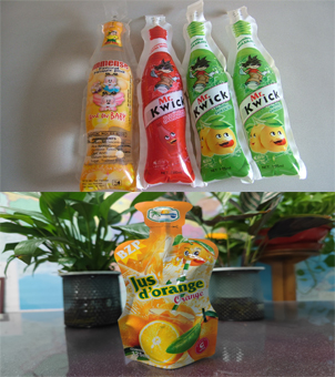
Versatile use: Can accommodate a variety of packaging formats, including bottles, pouches, and cartons, ideal for a wide range of beverage types.


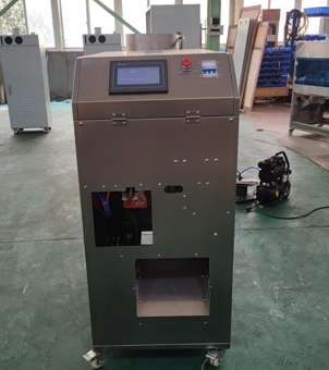
  • ketchup packing machine

    For the production of spout pouch liquid packaging.

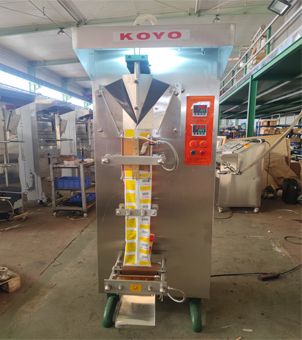
  •    koyo sachet machine

    Used in sachet liquid packaging production.

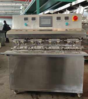
  •    pouch packing machine 

    Used for pouch liquid packaging production.


ross-industry applications

Beverage packaging equipment is not limited to juice and soda. It is versatile and can be used for:

Beverage manufacturing: Ideal for juices, tea drinks, dairy products, and more.

Food Industry: For sauces, condiments, and other liquid products.

hemical Industry: Dishwashing liquids, laundry detergents, cleaners, etc.

Health-conscious market: Meeting the demand for fresh, organic, and nutritious beverages.


  • doypack

    For packaging juice, yogurt, jelly, laundry detergent, etc.

  • PE Plastic Film Roll Bag
    For packaging Sachet Water/Juice/Milk, etc.

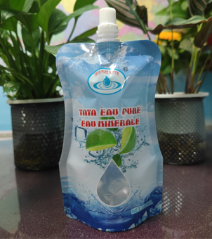
  • Special-Shaped Bags
    For packaging juice, water, milk and other liquids.


Market Outlook and Trends

The market for automated beverage packaging solutions is booming, driven by consumer preferences for convenience and health. Here are the factors shaping the future:

Large-scale production: Equipment is trending toward larger capacities to optimize costs and meet large-scale production needs.

Smart technology integration: Modern machines feature IoT connectivity, real-time data monitoring, and AI-driven customization.

Sustainability focus: Innovations in eco-friendly packaging and energy-efficient operations are gaining traction.

Our Latest Innovations

At KOCO, we are committed to pushing boundaries. Our latest equipment combines advanced automation with a user-friendly interface to simplify operations while increasing efficiency. Whether you need a stand-alone juice packaging machine or complete juice treatment equipment, our team of experts will work with you to design the perfect solution for your business.

Conclusion

The beverage industry is rapidly evolving, and so is the technology that drives it. By investing in modern, versatile equipment, businesses can stay ahead of the curve while meeting consumer demands for quality and sustainability. Are you ready to change your beverage production? Let's build the future together!


Contact number: 0086-19159001917

Main components of falling ball impact

2025-04-11

The falling ball impact tester is mainly used for impact strength test of plastics, building materials, ceramics, acrylic, glass, coatings, hardware and other products.

Test standard: GB/T9962-1998, GB/T9962-1999, JIS-K6745, A5430

Test principle: Cut a certain size of polyvinyl chloride hard sheet sample, hold the sample on the chuck of the falling ball impact tester, select a suitable steel ball and install it on the electromagnetic device, release the steel ball, let the steel ball fall freely in the center of the sample, observe the damage of the sample after impact, and calculate the damage rate after multiple tests.

Main components:

1. Main unit: intelligent operating system with pneumatic clamping and electromagnetic adsorption. In order to ensure the stable performance of the main unit, the pneumatic components used inside are all imported brands from abroad, and for the convenience of operation, a "ring light" is equipped in the middle, which is very humanized. Its shell is made of sheet metal spraying. Compared with the various stainless steel products that are the same on the market, it is not only more durable in overall performance, but also novel in appearance.

2. Steel ball: All steel balls used are of domestic unified standard specifications. Bearing steel is customized in a professional steel ball manufacturer, so the weight and diameter of the steel ball can be consistent with the test standards. Although the cost of choosing such a steel ball is much higher, it is durable and can ensure the accuracy of the experimental data

3. Foot switch: It has two opening methods: manual and foot pedal. However, since the foot pedal is more convenient for people to operate during the test, the entire test process is more humane.

4. Positioning device: The central positioning device is used, and the intelligent operation ensures the accuracy and reliability of the experimental results. It is also equipped with a protective device to make users safer during the operation and avoid similar situations where the steel ball accidentally hits people.

Falling Ball Impact Tester


Email: hello@utstesters.com

Direct: + 86 152 6060 5085

Tel: +86-596-7686689

Web: www.utstesters.com


Angle Steel Telecommunication Tower Antenna Pole Loading Capacity

2025-04-11

To determine the loading capacity of an Angle Steel Tower antenna pole, a comprehensive structural analysis considering various factors is essential. Here's a structured approach:

1. Material Properties

  • Steel Grade: Identify the steel grade (e.g., ASTM A36, A572) to determine yield strength (Fy), ultimate tensile strength (Fu), and modulus of elasticity (E).

  • Corrosion Considerations: Account for environmental factors that may reduce material thickness over time.

2. Geometric Properties

  • Member Dimensions: Cross-sectional area (A), moment of inertia (I), radius of gyration (r), and slenderness ratio (KL/r

  • KL/r

    KL/r) for each angle member.

  • Tower Configuration: Height, base width, bracing pattern, and leg spacing influence stability and load distribution.


  • angle steel telecom antenna tower

3. Load Types and Calculations

  • Dead Load: Weight of the tower, antennas, and permanent fixtures.

  • Live Load: Temporary loads (e.g., maintenance equipment).

  • Environmental Loads:

    • Wind Load: Calculated using wind speed (e.g., ASCE 7 or TIA-222), exposure category, drag coefficient (Cd), and projected area.

    • Ice Load: Adds weight and increases wind surface area; relevant in cold climates.

    • Seismic Load: Considered in earthquake-prone regions using seismic coefficients.

  • Dynamic Loads: Vibrations from antennas or wind-induced oscillations.

4. Structural Analysis

  • Axial Capacity: For compression members, check buckling using Euler's formula  (

    Pcr=π2EI(KL)2) and yielding (Py=FyA ).
  • Combined Stresses: Use interaction equations (e.g., AISC) for members under axial load and bending moments.

  • Connections: Verify bolt/weld capacities for shear, tension, and bearing.

5. Design Codes and Safety Factors

  • Relevant Standards: TIA-222 (telecom structures), ASCE 7 (environmental loads), AISC (steel design).

  • Load Combinations: Apply code-specified combinations (e.g., 1.2D + 1.6W).

  • Safety Factors: Incorporate factors of safety (e.g., 1.67 for AISC LRFD) to ensure reliability.

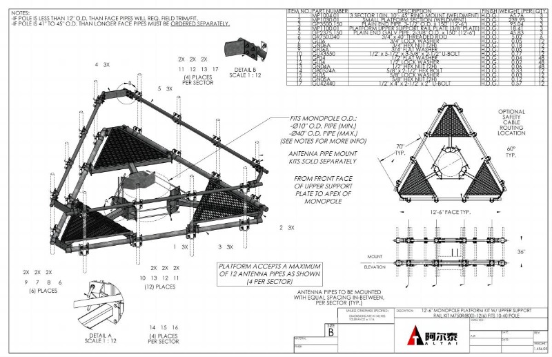
  • monopole telecom antenna tower

6. Example Calculation Outline

  • Wind Load Example:

    Fw=0.00256⋅Kz⋅Kzt⋅Kd⋅V2⋅Cd⋅A

    Where V is wind speed (mph), Kz is exposure coefficient, Cd is drag coefficient, and A is projected area.

  • Member Check: For a 50x50x5 mm angle (A=480 mm2r=9.8 mm), if KL/r=100, critical stress Fcr is calculated per AISC.

7. Software and Professional Input

  • Use structural analysis software (e.g., STAAD.Pro, SAP2000) for complex geometries.

  • Consult a licensed engineer for code compliance and final validation.

Key Considerations:

  • Foundation Design: Ensure the base can resist overturning moments and shear forces.

  • Dynamic Effects: Address potential resonance from wind or equipment.

  • Maintenance: Regular inspections to detect corrosion or damage.

Conclusion:

The loading capacity is a function of material strength, geometric efficiency, applied loads, and adherence to design codes. A detailed analysis balancing these factors ensures the tower's safety and functionality. Always involve a structural engineer for critical application. 


Learn more at www.alttower.com


Contact Us


telecom tower supplier

4 Legged Angle Steel Telecommunication Tower Design Condition Analysis

2025-04-09
  • Designing a 4-legged angle steel tower involves various considerations to ensure structural integrity, stability, and safety. Here are some key design conditions that are typically analyzed in the design process:
  •  
  • Load Analysis:

    • Dead Loads: Consider the weight of the tower structure itself, including all components such as steel angles, bolts, platforms, and antennas.
    • Live Loads: Evaluate the loads imposed by equipment, antennas, ice, wind, and any other dynamic loads the tower may experience during its service life.
    • Environmental Loads: Account for wind loads, seismic forces, ice loads, and any other environmental factors that may impact the tower's stability.

    • 4 leg angle steel telecom tower

    •  
  • Material Selection:

    • Choose appropriate angle steel sections based on their mechanical properties, including yield strength, tensile strength, and stiffness, to ensure the tower can withstand the calculated loads.
    • Consider factors such as corrosion resistance, weldability, and availability of the materials.
    •  
  • Geotechnical Analysis:

    • Conduct a soil analysis to determine the soil bearing capacity at the tower site, which influences the foundation design.
    • Evaluate the soil conditions to ensure the tower foundation can adequately support the applied loads.
    •  
  • Foundation Design:

    • Design a suitable foundation system based on the soil conditions and the loads imposed by the tower.
    • Ensure the foundation can distribute the loads effectively to prevent settlement or instability.
    •  
  • Structural Analysis:

    • Perform structural analysis using software tools to assess the tower's response to various loading conditions.
    • Check the tower members for stresses, deflections, buckling, and other structural performance criteria.
    •  
  • Connection Design:

    • Design connections between tower members, including bolted or welded connections, to ensure they can transfer loads effectively.
    • Consider factors such as connection detailing, material compatibility, and ease of fabrication and erection.

    • angle steel antenna tower telecommunication

    •  
  • Stability Analysis:

    • Assess the tower's stability against overturning, sliding, and buckling under different loading conditions.
    • Ensure that the tower design meets stability requirements to prevent structural failure.
    •  
  • Code Compliance:

    • Ensure that the tower design complies with relevant design codes and standards, such as local building codes, industry standards, and engineering guidelines.
    •  
  • Safety Factors:

    • Apply appropriate safety factors to account for uncertainties in loading conditions, material properties, and other design parameters.
    • Verify that the tower design provides an adequate level of safety for its intended use.
    •  
  • By carefully analyzing these design conditions and factors, engineers can develop a robust and safe 4-legged angle steel tower design that meets structural requirements, performance criteria, and safety standards for its intended application.


Learn more at www.alttower.com


Contact Us


telecom tower supplier

Design Considerations for Height in Angle Steel Communication Towers

2025-04-09

When designing the height of an angle steel communication tower, a comprehensive approach is required to balance technical, structural, regulatory, and environmental factors. Below is a structured overview of key considerations:

1. Purpose and Coverage Requirements

  • Antenna Functionality: Ensure the height accommodates the required elevation for antennas (e.g., cellular, TV, microwave) to achieve optimal signal coverage and line-of-sight (LOS) for microwave links.

  • Terrain and Obstacles: Account for natural or man-made obstructions (e.g., hills, buildings, trees) that may necessitate greater height for clear signal propagation.

2. Regulatory and Zoning Constraints

  • Aviation Regulations: Adhere to height restrictions near airports (e.g., FAA guidelines in the U.S.) to avoid interference with flight paths.

  • Local Zoning Laws: Comply with municipal regulations on maximum structure heights and environmental impact assessments (EIA) for tall towers.

  • Permitting: Secure necessary permits, which may involve public consultations for visually intrusive structures.


  • 4 leg angle steel tower telecom

3. Structural Design and Integrity

  • Wind and Seismic Loads: Calculate wind pressure using local wind speed data (e.g., ASCE 7 standards) and consider seismic activity for dynamic load analysis.

  • Foundation Design: Ensure the foundation (e.g., deep piles, reinforced concrete) can handle increased overturning moments and shear forces from greater heights.

  • Material Strength: Use appropriately graded steel sections and bracing systems to resist buckling, sway, and torsional stresses.

  • Dynamic Stability: Address natural frequency and vibration risks (e.g., vortex shedding) to prevent resonance.

4. Environmental and Climatic Factors

  • Wind and Ice Loads: Incorporate regional wind zones and ice accumulation risks, which add structural weight and wind drag.

  • Temperature Effects: Allow for thermal expansion/contraction in design tolerances.

  • Corrosion Resistance: Apply protective coatings (e.g., galvanization) to mitigate corrosion from moisture, salt, or pollution.

5. Economic Considerations

  • Cost-Benefit Analysis: Balance height-related costs (materials, foundation, transportation) against coverage benefits.

  • Transportation and Logistics: Consider limitations on steel section sizes due to road transport regulations and crane availability.

6. Safety and Maintenance

  • Lightning Protection: Install grounding systems and lightning rods, especially for taller towers.

  • Climbing Safety: Design safe access (e.g., ladders, platforms) and fall-protection systems for maintenance.

  • Ice Shedding: Implement measures to prevent ice buildup or safely shed ice to avoid hazards.

7. Future Expansion and Flexibility

  • Modular Design: Allow for future height extensions or additional antenna mounts without structural retrofitting.

  • Load Redundancy: Reserve capacity for new equipment (e.g., 5G antennas) and evolving technologies.


  • angle steel telecom antenna tower

8. Aesthetic and Social Impact

  • Visual Blending: Use camouflage (e.g., lattice designs, paint schemes) in sensitive areas (urban, scenic) to reduce visual intrusion.

  • Community Feedback: Engage stakeholders early to address concerns about aesthetics or property values.

9. Installation and Lifespan

  • Erection Feasibility: Plan for construction challenges (e.g., crane reach, assembly sequencing) for very tall towers.

  • Durability: Ensure a design lifespan (typically 25–50 years) with minimal maintenance through robust materials and coatings.


Design Factor Integration Example:

A tower in a coastal urban area might prioritize corrosion-resistant materials, strict height limits due to nearby airports, and aesthetic blending with surroundings. Meanwhile, a rural microwave relay tower would emphasize LOS clearance, wind/ice loads, and minimal foundation costs.

By systematically addressing these factors, engineers can optimize tower height for functionality, safety, compliance, and cost-effectiveness.


Learn more at www.alttower.com


Contact Us


telecom tower supplier

Furniture Universal Testing Machine GT-LA10 in Detail

2025-04-08
Furniture Universal Testing Machine GT-LA10 in Detail

We see furniture everywhere in our daily life, tables, desks, beds and chairs. When in use these pieces of furniture need to undergo some rigorous testing to ensure that they are able to withstand various external forces in actual use. So what kind of testing does furniture need? Our Furniture Universal Testing Machine GT-LA10 is a versatile, highly accurate and flexible machine capable of performing a wide range of furniture testing needs. This article will detail the applications, features and standards of the Universal Tables And Chairs Testing Machines GT-LA10.


Universal Tables And Chairs Testing Machines


Understanding Furniture Universal Testing Machine


Furniture Universal Testing Machine is used to test the mechanical properties of tables, desks, beds and chairs. It can perform the horizontal static load, vertical static load, impact test and durability test. These tests cover a variety of external forces that furniture may encounter in daily use, such as bearing heavy loads for a long time, sudden impacts, and wear and tear from repeated use. Through these tests, the load-bearing capacity, stability and durability of the furniture are understood so as to ensure whether the products comply with the relevant standards.


Main Features


1. Frame structure design

GT-LA10 Universal Tables And Chairs Testing Machine adopts the frame made of industrial aluminum, which is sturdy, durable and beautiful.

2. Multi-group cylinder configuration
Up to 7 groups of cylinders are installed, one group on each side and three groups on the upper frame. All cylinders can be adjusted up and down, front and back, covering all mounting surfaces. Seven groups of cylinders can be linked or run independently, with a certain degree of flexibility and durability.

3. Bottom fixing block adjustable
The position of the bottom fixing block can be adjusted according to the different specifications of the samples to increase the stability and accuracy of the testing process.

4. PC controller
PC controller controls the movement of the instrument, which is intuitive and easy to operate.

5. High Precision Pressure Regulation
Furniture Testing Machine adopts precision regulator to adjust the pressure and change the loading force value; high-precision force sensor senses the force value in real time, and each load group is individually adjusted and controlled, so the loading force is stable and reliable.

6.Removable loading pad
Removable loading pad, can easily replace different loading pads to meet different test requirements.

Relevant standards


1. Tables & Desks&Storage Units:

EN1730-2012 Section 6.2, 6.3, 6.4,6.5, 6.6, 7.2, 7.3 ,
BS EN 15372-2016 Test1, Test2,Test3,Test5, Test6,Test8,Test10,
AS NZS 4610.3-1999 Annex B,D,E,G,N,P,R
AS NZS 4442-199  Annex A,B,H,J
EN527-3, EN581-3, GB/T 10357.1,、
BIFMA X5.5 - 2014, BIFMA X5.6 - 2010, BIFMA X5.9 - 2012,

2. Chairs:
EN 1728-2012 Section 6.4, 6.5, 6.7, 6.12, 6.15, 6.16, 6.17, 6.24,7.3, 7.4,7.9, 8.2, 8.4.1,8.5 , 8.8(6.25, 6.26 optional accessories)
EN581-2-2015 (corresponding with EN1728-2012),
EN1335-3 -2009 Section 7.2.1, 7.2.2, 7.3.1
EN 1729-2-2012 Section 5.3.2, 5.3.3, 5.3.5, 5.3.6, 5.3.7(5.3.8 need the optional accessories)
EN 16139-2013 (corresponding with EN1728-2012)
ISO 7173-1989 Section 7.1, 7.2, 7.3, 7.5, 7.6, 7.7, 7.8, 7.10 (7.11,7.12 need the optional accessories)
BS5459-2-2000 Section A5.1 5.2 (A5.3, A7.4 need the optional accessories)
BS5459-2-2000 Section  A5.2,
BIFMA X5.1 - 2017 Section 7, 10.3
QB/T 2280-2007 Section 6.6.4, 6.6.3, 6.6.9 , 6.6.13.1
GB/T 10357.3 -2013 Section 4.3, 4.4,4.7,4.8,4.10,4.11,6.9 (4.13,4.14 need the optional accessories)

3. Bed:
EN 747-2 Section 5.4,5.5,5.6.1,5.7,5.8

What is a MIT Type Paper Folding Endurance Tester GT-N16–A Complete Guide

2025-04-08
What is a MIT Type Paper Folding Endurance Tester GT-N16–A Complete Guide

Paper products are folded or bent many times during daily use, such as book flipping, box folding, print processing, etc. The MIT Folding Endurance Tester evaluates the folding resistance of a material under a certain tension by simulating the folding stress of paper products in real applications. Next, we will take a closer look at the Paper Folding Endurance Tester GT-N16.


MIT Folding Endurance Tester


What is the MIT Folding Endurance Tester


Paper Folding Endurance Tester GT-N16 is a high-precision paper and cardboard folding resistance testing equipment, with a number of functions such as parameter testing, conversion, adjustment, display and memory. Paper Folding Endurance Tester is compact, lightweight and feature-rich, with horizontal design and stable performance, so the tester is suitable for different papers and cardboards.

Mit Paper Folding Endurance Testing Principle

The working principle of the folding endurance test for paper is based on the mechanics of materials and the analysis of the physical properties of paper, and the testing process is as follows:

The paper or cardboard sample is fixed in the clamping device of the tester.

A certain amount of tension is provided by a spring system, which causes the sample to be folded under controlled tension.

The Mit Paper Folding Endurance Tester 's folding device performs reciprocal folding to simulate the stresses on the paper or cardboard in actual use.

The sample is subjected to constant folding stresses and eventually breaks due to fatigue, and the tester records the total number of folds endured.

Test data is usually expressed in two ways:

Number of folds - a direct record of the number of folds the sample can withstand during the test.
Logarithmic value of the number of double folds (base 10) - mathematically expresses the folding resistance data, which is more suitable for laboratory analysis and comparative studies.

The higher the folding resistance value, the stronger the folding resistance of the material.

MIT Folding Endurance Tester Technical Parameters

The main technical parameters of GT-N16 folding endurance tester paper are as follows:

Measuring range: 0 - 99999 times
Folding Angle: 135±2
Folding frequency: 175±10 times/minute
Folding head width: 19±1mm
Folding radius: 0.38±0.02mm
Spring tension: 4.91N~14.72N, every increase of 9.81N tension, the spring compression is reduced by at least 17mm.
Folding mouth gap: 0.25, 0.50, 0.75, 1.00mm (four ranges)
Change of tension force caused by eccentric rotation of clamping folding head: ≤0.343N

Conformity standards


The Mit Paper Folding Endurance Tester GT-N16 complies with a number of international and domestic test standards, including:


  • ISO 5626 (International Standard for Paper Folding Resistance Testing)
  • GB/T 2679.5 (China's national cardboard folding resistance test standard)
  • QB/T 1049 (Light Industry Folding Resistance Test Standard)
  • ASTM D2176 (American Society for Testing and Materials standard)


These standards ensure that the GT-N16 folding endurance test for paper's test results are accurate, repeatable and able to meet the quality control needs of different industries.


How to Operate Mit Paper Folding Endurance Tester

Acceptance
  • Check accessories: 1 set of wrench, 4 sets of clamps, 3pcs of weights.
  • Confirm power supply and connect, turn on the power switch.
  • Adjust the machine level according to the level meter.

Operation


Mounting the specimen:
According to the thickness of the specimen, select the corresponding fixture and mount the fixture on it.
Reset the fixture and start installing the specimen.
Fix the specimen.

Install the weights.


Parameter setting:
Click “SETTING” , there are two modes, “Counter” and “Timer” mode, select the “Counter” mode, set the counting times.
Set the speed, click “TEST” to return to the test interface, click “Zero” to clear, click “TEST” to start the test.
The test will automatically stop when the test is completed, and it will also stop when the specimen breaks during testing.

Analysis of Market Demand and Product Features of Chemical Process Pumps

2025-03-31

Introduction

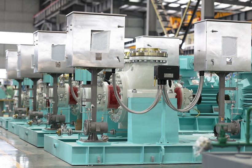
With the continuous advancement of global industrialization, the demand for process pumps in the chemical industry continues to grow. As a critical fluid transfer device in chemical processes, chemical process pumps play a vital role in maintaining production continuity, improving efficiency, and ensuring safety and environmental compliance. This article will explore the classification, key features of current chemical process pumps, and the latest trends in market demand.
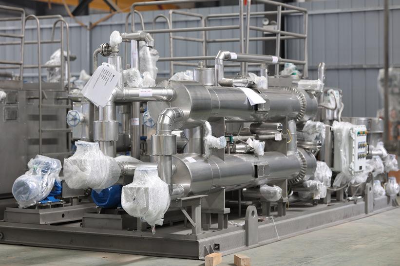


Classification of Chemical Process Pumps and Standards

1. Classification by Working Principle

   - Centrifugal Pumps: Rely on the centrifugal force generated by a high-speed rotating impeller to transfer the fluid. These are the most common type of process pumps in the chemical industry, suitable for low-viscosity fluids with minimal particulates.

   - Positive Displacement Pumps: Including gear pumps, screw pumps, and plunger pumps, these pumps transfer fluid through volume changes in the pump chamber, making them suitable for high-viscosity fluids or applications requiring precise metering.

   - Magnetically Driven Pumps: Utilize magnetic couplings to transfer power, providing strong sealing capabilities. They are ideal for handling toxic, flammable, and explosive hazardous chemical fluids.


2. Classification by Material

   - Metallic Pumps: Such as stainless steel and alloy pumps, are primarily used for transporting highly corrosive acidic and alkaline media. The choice of metallic material depends on the corrosiveness and temperature requirements of the medium.

   - Non-Metallic Pumps: Such as fluoroplastic and ceramic pumps, offer superior corrosion resistance and are used for handling highly corrosive fluids, particularly in specialized applications where metallic pumps may not suffice.


3. Classification by Drive Type

   - Electric Pumps: Driven by electric motors, these are the most common type of process pumps, suitable for various conditions, especially in continuous chemical operations.

   - Pneumatic Pumps: Powered by compressed air, they are typically used in flammable or explosive environments, offering higher safety as they do not require electricity.

   - Hydraulic Pumps: Driven by hydraulic systems, they are suitable for high-pressure applications, often used in processes requiring high delivery pressure.

4. Classification by Installation Method

   - Horizontal Pumps: The pump shaft is installed horizontally, suitable for large spaces with easy maintenance, commonly found in large chemical plants.

   - Vertical Pumps: The pump shaft is installed vertically, ideal for limited space, usually used for liquid transfer from underground tanks or deep wells.


2. Key Features of Chemical Process Pumps

1. Material Selection and Corrosion Resistance

   Chemical process pumps are typically made from high-performance materials to withstand various complex chemical media. Common materials include stainless steel, Hastelloy, and titanium alloys, known for their excellent corrosion resistance, allowing them to operate long-term in harsh environments like strong acids and alkalis. Additionally, non-metallic materials such as fluoroplastics are widely used in specialized applications, offering exceptional corrosion resistance and wear properties.


2. High Efficiency and Energy Conservation

   As energy conservation becomes a global trend, the efficiency of chemical process pumps has garnered significant attention. Modern process pumps, optimized in design and equipped with high-efficiency motors, effectively reduce energy consumption. In large-scale chemical facilities, these efficiency improvements not only lower operational costs but also reduce carbon emissions, aligning with the development direction of green chemistry.


3. Reliability and Durability

   Operating in harsh industrial environments, chemical process pumps require high reliability and durability. Modern pumps often incorporate advanced sealing technologies and wear-resistant designs to extend service life and reduce maintenance frequency. Additionally, intelligent monitoring systems can monitor operational status in real-time, providing early warnings for potential failures, further enhancing system reliability.


3. Market Demand Analysis

1. Global Market Growth

   According to market research reports, the global chemical process pump market is expected to maintain stable growth in the coming years. The Asia-Pacific region, driven by accelerated industrialization, especially in emerging markets like China and India, is experiencing the fastest growth in demand for chemical process pumps. In contrast, the European and North American markets focus primarily on technological upgrades and efficiency improvements, with high demand for high-performance, energy-efficient chemical pumps.


2. Green Chemistry and Sustainable Development

   Stricter environmental regulations are accelerating the transition of chemical companies toward green chemistry, creating new market opportunities for energy-efficient chemical process pumps. Many companies are seeking low-energy, high-efficiency pump products to reduce their carbon footprint and comply with global environmental standards. Simultaneously, the concept of a circular economy is driving the development of the chemical pump market, requiring pumps with longer lifespans and higher resource utilization efficiency.


3. Regional Market Demand Differences

   There are significant differences in the demand for chemical process pumps across different regions. The Asia-Pacific region, with its large-scale new projects, focuses on cost-effectiveness and bulk procurement. The European market places greater emphasis on technological advancement and environmental compliance, preferring high-efficiency, energy-saving pump products. The North American market, while maintaining high standards, is gradually moving towards smart equipment, with increasing demand for automation and intelligent monitoring systems.


Conclusion

As the global chemical industry evolves, the demand for chemical process pumps is becoming increasingly diversified. From material selection to energy efficiency improvements and regional market differences, the product features of chemical process pumps are closely linked to market demand. For chemical companies, selecting the right process pump can not only enhance production efficiency but also meet environmental requirements, helping them stay competitive in a rapidly changing market.
 

References

1. Market Research Report: "Global Chemical Process Pump Market Analysis," 2023 Edition.

2. Industry Analysis Article: "Technological Innovations and Applications of Chemical Process Pumps," published in 2022.

3. Academic Research: "Driving Factors of Chemical Process Pump Demand Growth in Emerging Markets," 2021.

4. Industry Trends Report: "Market Opportunities in Green Chemistry and Sustainable Development," 2023.

5. Internal Company Data: "Regional Market Demand Analysis for Chemical Pumps," Q2 2024 Report.

Tags